Oscilloscope Front-End Circuit Design
2023, Mar 27
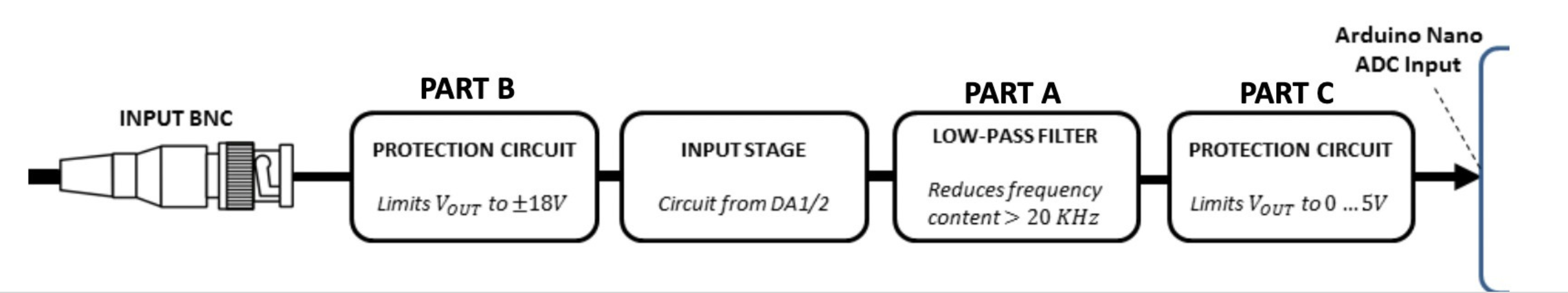
This project involved designing the front-end circuit and PCB layout for an externally powered oscilloscope, incorporating two input ranges (1x and 10x modes), frequency attenuation above 20 kHz, and both AC and DC coupling capabilities.
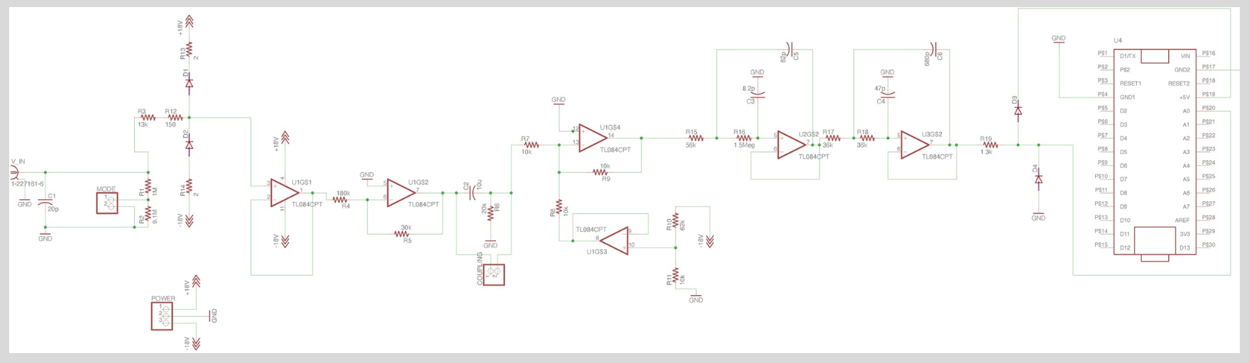
Circuit Design
- The circuit uses low-pass filters, adders, buffers, and SPST switches to implement the functionality of the oscilloscope front-end.
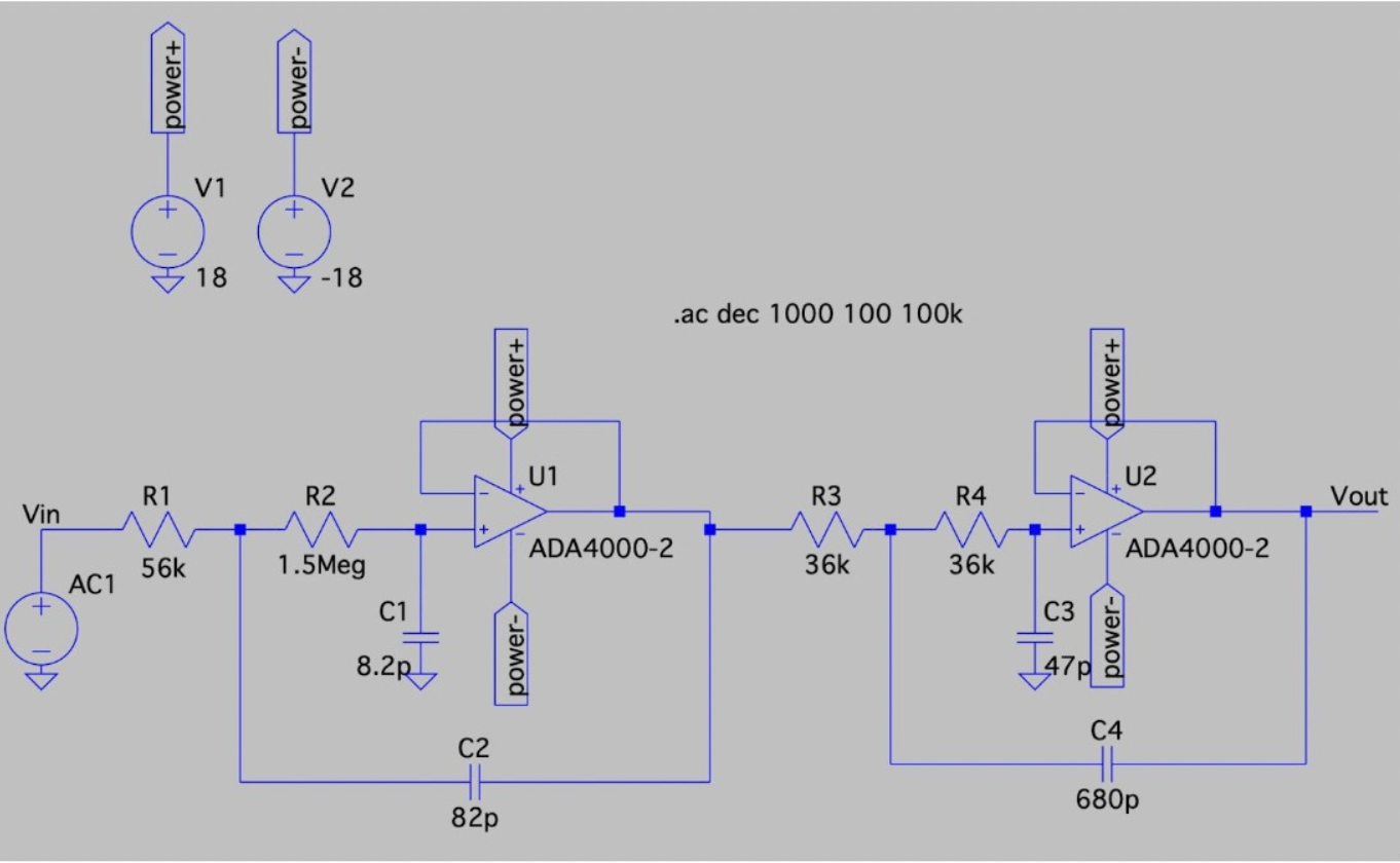
- LTspice simulations were conducted to validate the design before creating the PCB layout.
- The low-pass filter was specifically designed using the Analog Filter Wizard to attenuate content frequencies above 20 kHz.
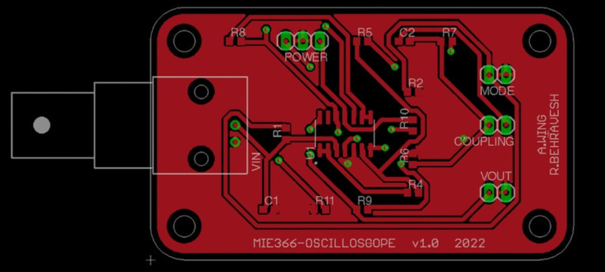
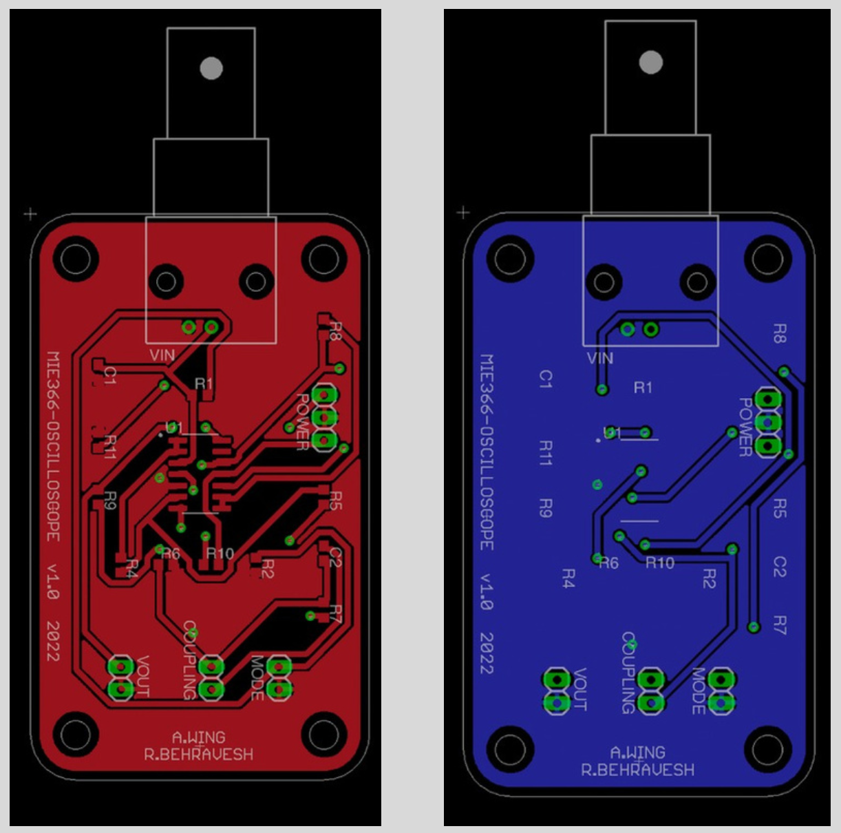
PCB Layout
- The PCB was designed using Autodesk Eagle, employing surface-mount technology (SMT) to achieve a compact and efficient design.
- The design accommodates both 1x and 10x input modes and integrates AC/DC coupling switches.
Simulation Results
- The circuit was successfully simulated on LTspice, with accurate switching between the two input modes and correct AC/DC coupling behavior.
- The design met the requirements for frequency attenuation and switching functionality.
This project showcases expertise in:
- Analog circuit design.
- PCB layout using SMT.
- Simulation and verification using LTspice.