Enhancing Safety in Surgical Robotics Using Virtual Fixtures
Overview
This project was completed at the University of Toronto in collaboration with the Wilfred and Joyce Posluns Centre for Image-Guided Innovation and Therapeutic Intervention (PCIGITI). It focuses on improving safety in robotic-assisted cranial surgery by building a real-time Unity simulation that acts as a digital twin for a bone-cutting surgical robot.
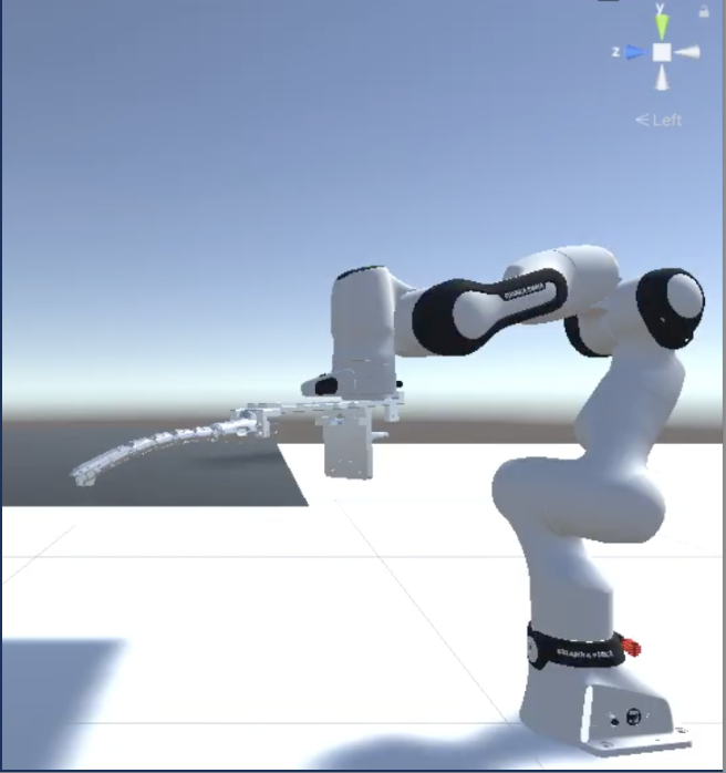
The robot is a 7-DOF Franka Emika Research 3 (FR3) arm fitted with a custom multi-jointed bone-cutting tool, used to assist surgeons performing craniotomies on infant skull models. The simulation mirrors the physical robot’s motion in real time and enforces forbidden-region virtual fixtures (FRVFs): when the simulated tool approaches a restricted area, the physical robot is stopped before any unsafe motion can occur.
System Architecture
- Physical Robot: Franka Emika Research 3 (FR3) with a custom 9-joint bone-cutting tool
- Simulation: Unity 2022.3 running a digital twin of the full robot-tool system
- Middleware: ROS connecting the physical and virtual subsystems via TCP
- IK Solver: Levenberg-Marquardt solver from the Robotics Toolbox for Python, converting Cartesian waypoints to FR3 joint angles
- Collision Detection: Unity monitors end-effector distance to a virtual fixture plane and publishes contact status to
/contact_status - Controller Inhibition: The physical robot’s ROS controller subscribes to
/contact_statusand blocks any motion command that would violate the virtual fixture boundary
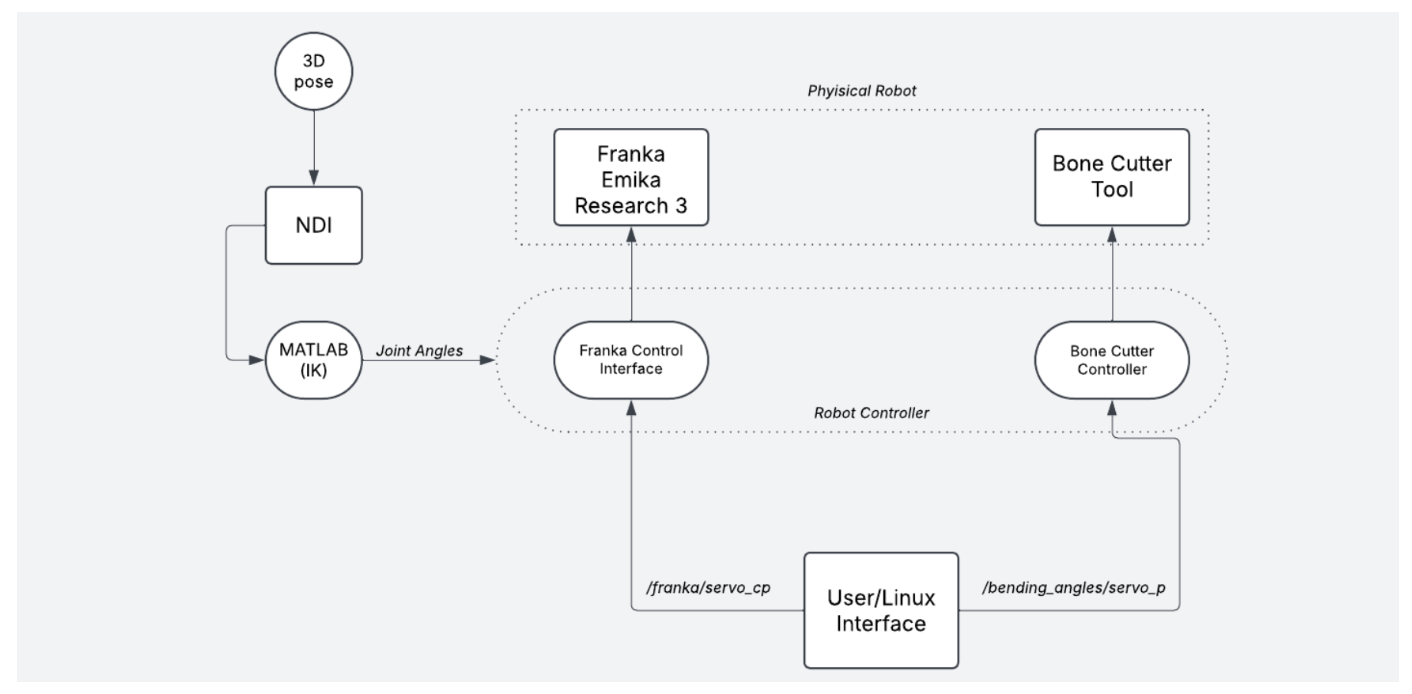
Existing system architecture
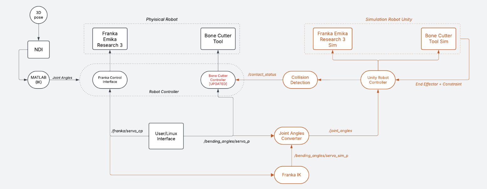
Proposed system architecture with Unity digital twin and collision inhibition layer
Virtual Model and Joint Mapping
The FR3’s URDF model was imported into Unity using the Unity URDF Importer, with each link represented as an ArticulationBody. The bone-cutting tool was modeled in SolidWorks, exported as a URDF, and attached to the FR3’s flange, giving the combined system 16 joints total.
Bending angle inputs (q1, q2) for the bone cutter are distributed across 9 tool joints using a proportional mapping:
- Joints 1-4: q1 / 4
- Joints 5-9: q2 / 5
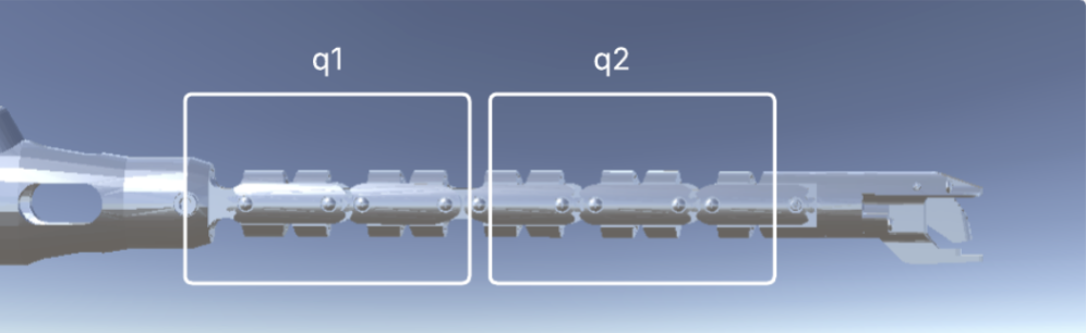
Bone cutter tool segments q1 and q2
Virtual Fixture and Collision Detection
A planar virtual fixture is placed in the Unity scene to represent a forbidden anatomical region (e.g., brain tissue beyond the bone surface). A contact event is triggered when the end-effector’s Y-coordinate falls within a threshold distance of the fixture plane.
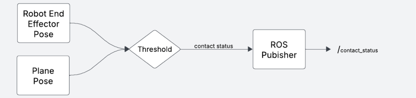
Virtual fixture boundary violation pipeline
When contact is detected, Unity publishes a signal on /contact_status. The physical robot’s controller reads this before executing any motion command. If a collision is flagged, the controller outputs:
RosBoneCutterController | Control permission denied.
If the simulation goes offline entirely, the controller defaults to halting all motion as a fail-safe.
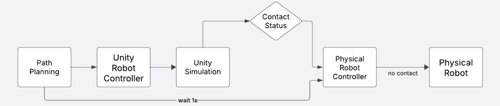
Controller inhibition pipeline upon collision detection
Results
Pose Matching: The Unity simulation accurately mirrored arbitrary physical robot configurations in real time across all tested poses.
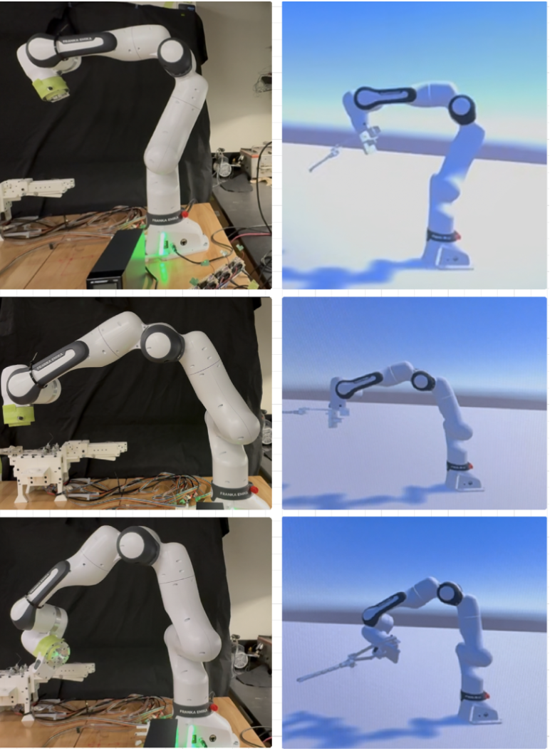
Comparison between physical and simulated FR3 configurations
Collision Detection: Across 5 test cases with varying bending angles, the system achieved 100% detection accuracy using a 5 mm threshold distance to the virtual fixture plane.
| Test | q1 | q2 | Distance to VF (cm) | Result |
|---|---|---|---|---|
| 1 | 3.0 | 3.0 | 1.20 | OK |
| 2 | 5.0 | 5.0 | 0.74 | OK |
| 3 | 7.5 | 7.5 | 0.45 | Contact Detected |
| 4 | 9.0 | 9.0 | 0.03 | Contact Detected |
| 5 | 10.0 | 10.0 | -0.11 | Contact Detected |
Collision Inhibition: In every case where the simulated tool violated the fixture boundary, the physical robot stayed stationary. No false positives or false negatives were observed. The system also handled edge cases near the detection threshold without flickering.
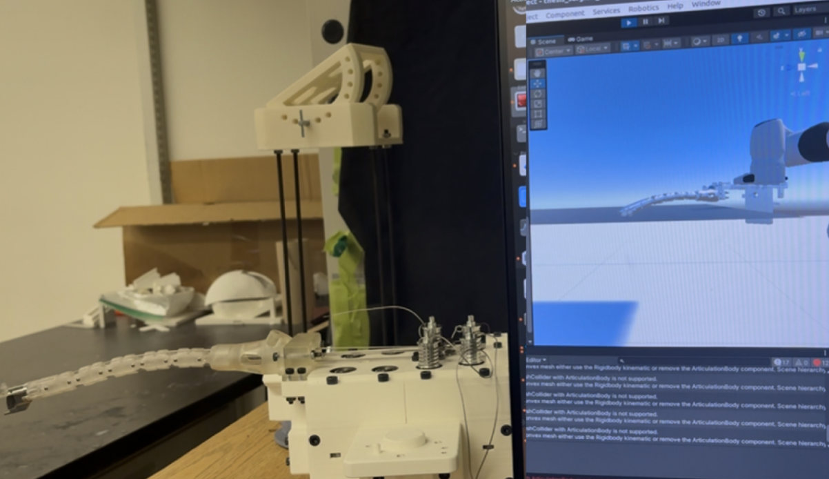
Simulated position prohibited on physical model
Inverse Kinematics: The external IK solver produced a consistent positional offset compared to the FR3’s internal solver, with average errors of 0.73 m (X), 0.54 m (Y), and -0.34 m (Z). The offset is systematic and could be corrected with a one-time calibration transform.
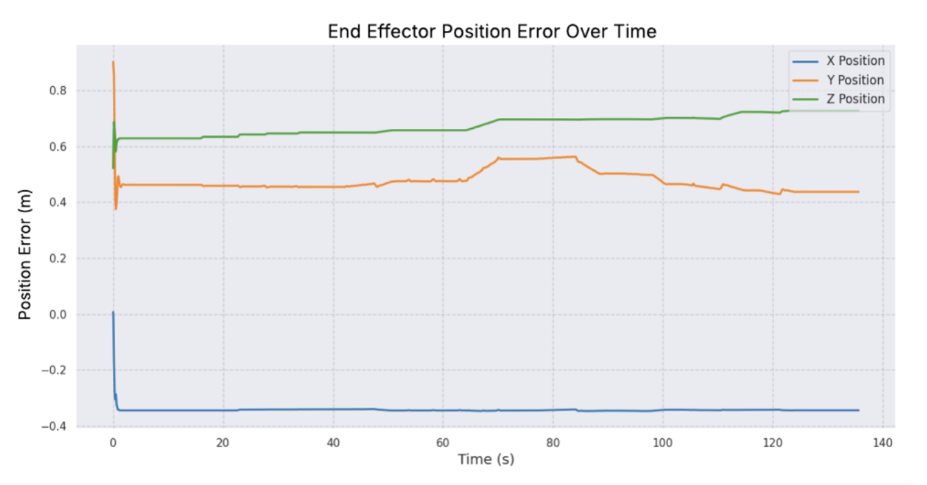
End-effector position error over time between implemented IK and physical robot
Future Work
- Multithreaded ROS execution to reduce latency and support true real-time monitoring
- Calibration routine to correct the IK offset between simulation and physical robot
- Extension of collision detection to 3D patient-specific anatomical models from CT scans
- NDI optical tracker validation of bone cutter position against Unity simulation
- Haptic feedback integration for surgical training applications